ULTRASONIC TESTING (UT)
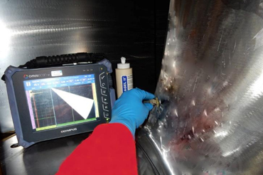
EIWAA Oil and Gas Services provides NDE Inspection as well as NDT Testing Services of Ultrasonic testing Inspection Services in Saudi Arabia. This is normally used for Storage tank inspection projects as well as pipeline Inspection Projects in Saudi Arabia. In Marine Services,our prestigious clients use our Rope Access Services in Saudi arabia to fulfill their welding inspection requirements by replacing scaffolding access. High frequency sound energy is utilized in ultrasonic testing services (UT) to perform measurements and examinations. Ultrasonic inspection has several applications, including material characterization, dimension measuring, and flaw assessment. A standard pulse/echo inspection configuration will be utilized to demonstrate the general inspection concept. High-frequency sound energy is used in ultrasonic testing to conduct inspections and collect data. Dimensional measurements, thickness, material characterization, flaw detection, and other inspections can be performed with ultrasonic testing.In recent years, there have been several advancements in ultrasonic non-destructive testing, ranging from using standard thickness to using more sophisticated techniques using multiple modes. Welding inspection of ultrasonic testing or ultrasonic scanning method known as shear wave testing, sometimes referred to as angle beam inspection. Shear wave testing, which comprises positioning a probe to the side of a weld and generating beams at an angle toward the weld, is typically required for complicated weld geometry and the presence of a weld crown or bead. Ultrasonic scanning inspection is an alternative volumetric inspection method for radiographic testing and its widely used in API 653 Inspection of Storage tank as well as API 570 Inspection for pipeline Inspection. Time-of-flight diffraction (TOFD), guided-wave ultrasonic and ultrasonic phased array inspection are a few more ultrasonic testing solutions.
ULTRASONIC SCANNING PROCEDURE REQUIREMENTS
Variation from ultrasonic testing procedure shall only be undertaken with the prior written approval of Client. Each variation shall be noted on the ultrasonic report and a relevant test technique or procedure produced if required. Coupland’s such as SAE 40 oil, Ultra gel, cellulose paste or equivalent may be used. The rate of search unit movement for examination shall not exceed 150 mm / second unless calibration shall be verified at the intended scanning speed. The volume shall be examined by moving the search unit over the examination surface to scan the entire examination volume. Each pass of the probe shall overlap a minimum of 50% of the probe (piezo-electric element dimension perpendicular to the direction of the scan). For weld testing, scanning shall be done from both the sides of the same face of the material. In case both the sides of the same face are inaccessible the information shall be recorded in the report. For plate lamination testing, using a straight beam probe, the area to be tested shall be scanned in a grid pattern. The grid dimensions shall be 225 mm width by 225 mm breadth unless otherwise previously specified and agreed with the Client. UT Scanning Service shall be performed at a gain setting of at least two times the primary reference level. The evaluation shall be performed with respect to the primary reference level. UT Scanning surface shall be free of weld spatter, dirt, and corrosion products.

