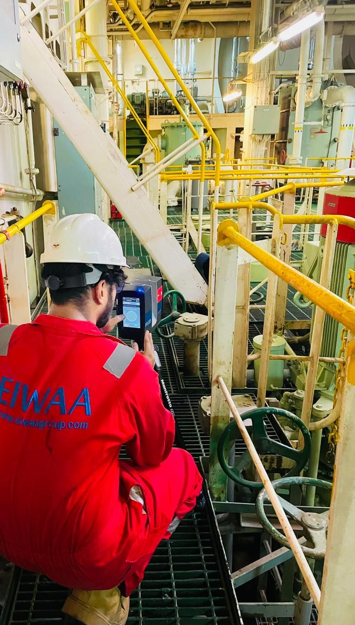
How to perform 3D Laser scanning Survey in marine retrofitting solutions of Hull Air Lubrication System
Please note that all the following areas will need to be scanned with the provided settings for capturing in FARO Laser Scanner.
- Resolution: ¼
- Quality: 4x
- COLOURED
TANK TOP
- BALLAST PUMPS -Suction/ discharge of the pumps with clear view of all valves. (Several scans required around them)
- BALLAST MAIN LINE AND CONNECTION TO W.B.TKS AND OVERBOARD PIPES -We need the most possible scans near them with clear sight of connections.
- BALLAST STRIPPING EDUCTORS -Several 3D Rendering Service scans required around them.
- BILGE & FIRE PUMPS -Suction/ discharge of the pumps with clear view of all valves and connections.
- OVERBOARDS PIPES
- APT BALLAST LINE – Scans will need to take place through/ across apt line(under the panels).
Important note: In order to have a clear pipe and connection sight and in order to avoid any blind spots at the tank top area, require all the FLOOR PANELs to be removed prior 3D scanning survey.
LOWER FLOOR
- BALLAST PUMPS-Suction/ discharge of the pumps with clear view of all valves. (Several scans required around them).
- BILGE, FIRE & G.S PUMPS -Suction/ discharge of the pumps with clear view of all valves (Several scans required around them).
- C.S.W PUMPS- Suction/discharge connection points.
- POTENTIAL INSTALLATION AREAS-All clear spaces at the Lower Floor area are mandatory to be scanned in order to find a suitable installation area.
- ENGINE ROOM AREA IN FRONT OF MAIN ENGINE -All the available space in front of main engine.
- SIDE STRINGER DECKS (If any) -3D Rendering Service Scans will need to be performed on stringer decks and below of them.
Important note: All the 3D Rendering Service scanning procedure must be completed with all FLOOR PANELS removed and all pipe connections and routes to have adequate view from Floor Deck level.
ENGINE ROOM
All casing areas need to be scanned with the provides setting for capturing in FARO laser Scanner.
- Resolution: 1/5
- Quality: 4x
- COLOURED
LOWER FLOOR
AFT, PORT & STBD SIDE OF MAIN ENGINE to be scanned for view of possible obstacles and pipes that may interfere the installation process.
OTHER DECKS (3RD TO 2ND)
All the following areas to be scanned with the provided settings for capturing in FARO laser Scanner
- Laser Scanner Resolution: 1/5
- Quality: 4x
- COLOURED or NON COLOURED based on the available provided time.
- ALL SECONDARY PUMPS (C.F.W, AIR RESERVOIR)
- ENGINE ROOM SKYFALL
ADDITIONAL INFORMATION
- SPARE CHANEL PORTS (incl. photos)
- MAIN SWITCHBOARS SPARE BREAKER LIST (incl. photos)
- Also relevant drawings if available onboard

